The Schlüsselgerät 41 (SG-41) Technical Description
The Schlüsselgerät 41 (SG-41) is a German World War II mechanical pin wheel cipher machine, designed by Fritz Menzer in 1941 as a more secure successor to the Enigma and manufactured by Wanderer Werke, a typewriter manufacturer. It uses a pin and lug (pin wheel) principle rather than classic wired rotors, and prints both plaintext and ciphertext on paper tapes instead of using lamps. Its design—compact, rugged, and crank driven—was optimized for field use by the Abwehr and other units, though only around 1000–1500 units were delivered before the end of the war.
Due to wartime shortages of lighter metals like aluminium and magnesium, it ended up weighing approximately 13.5 kilograms (30 lb) which made it too heavy for carrying any distance, a fact which may well have contributed to it’s lack of production.

Description of use
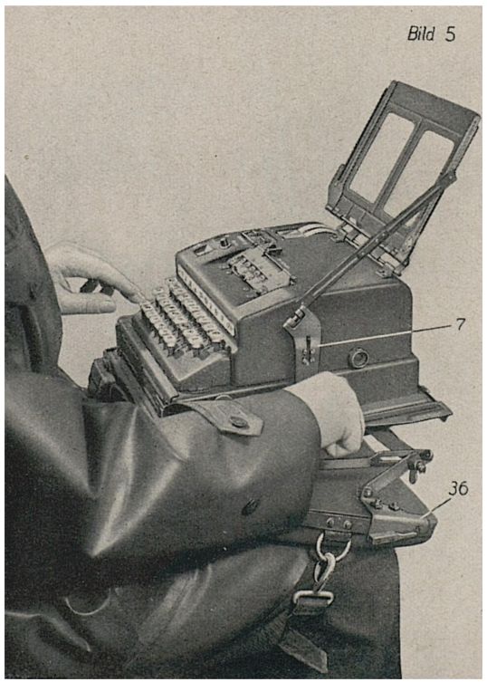
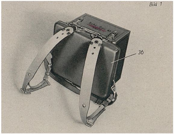
In operation, the SG 41 is placed either on a flat surface, with the operator facing the keyboard and the crank on the right. Alternatively, a thigh pad attachment with straps was available for the “portable” version. The operator sets the machine’s internal keying elements (pin wheels, lugs, and starting positions), inserts paper tapes and ink, and then firstly presses a key before turning the crank. Each full crank turn advances the internal mechanism, computes a substitution, and prints both the input character and the resulting output character on separate tapes, enabling immediate verification and a permanent record. The machine can be used for both encryption and decryption by applying the same key settings and operating sequence.
The interior
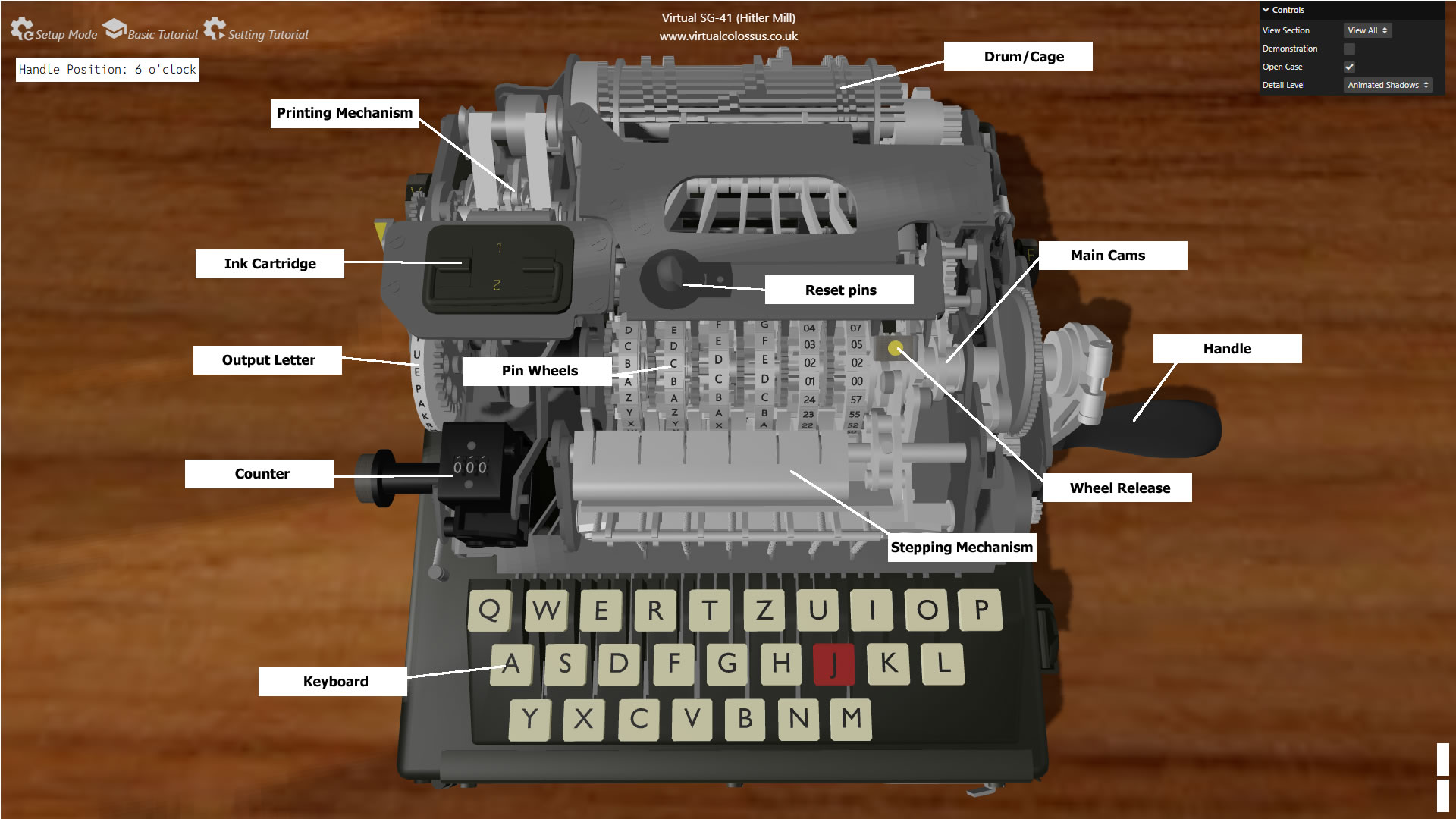
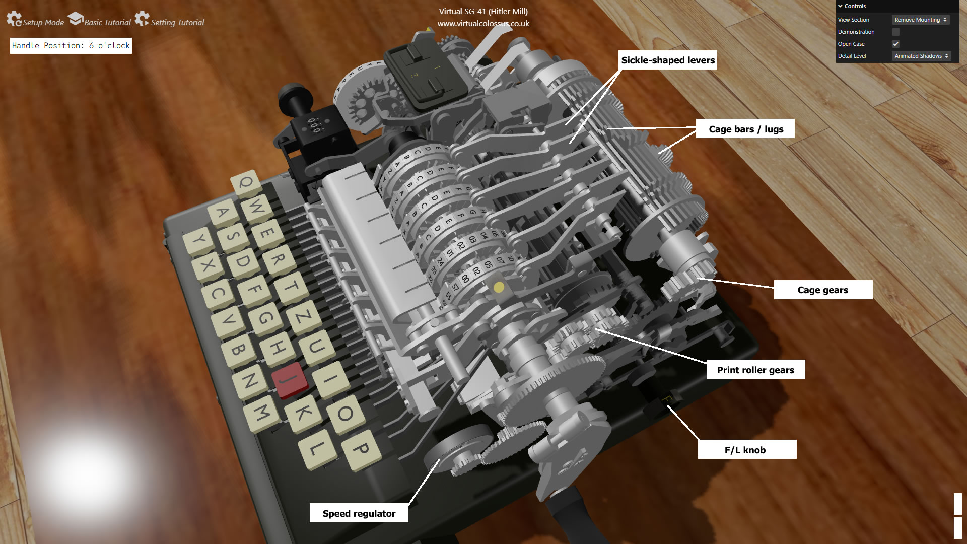
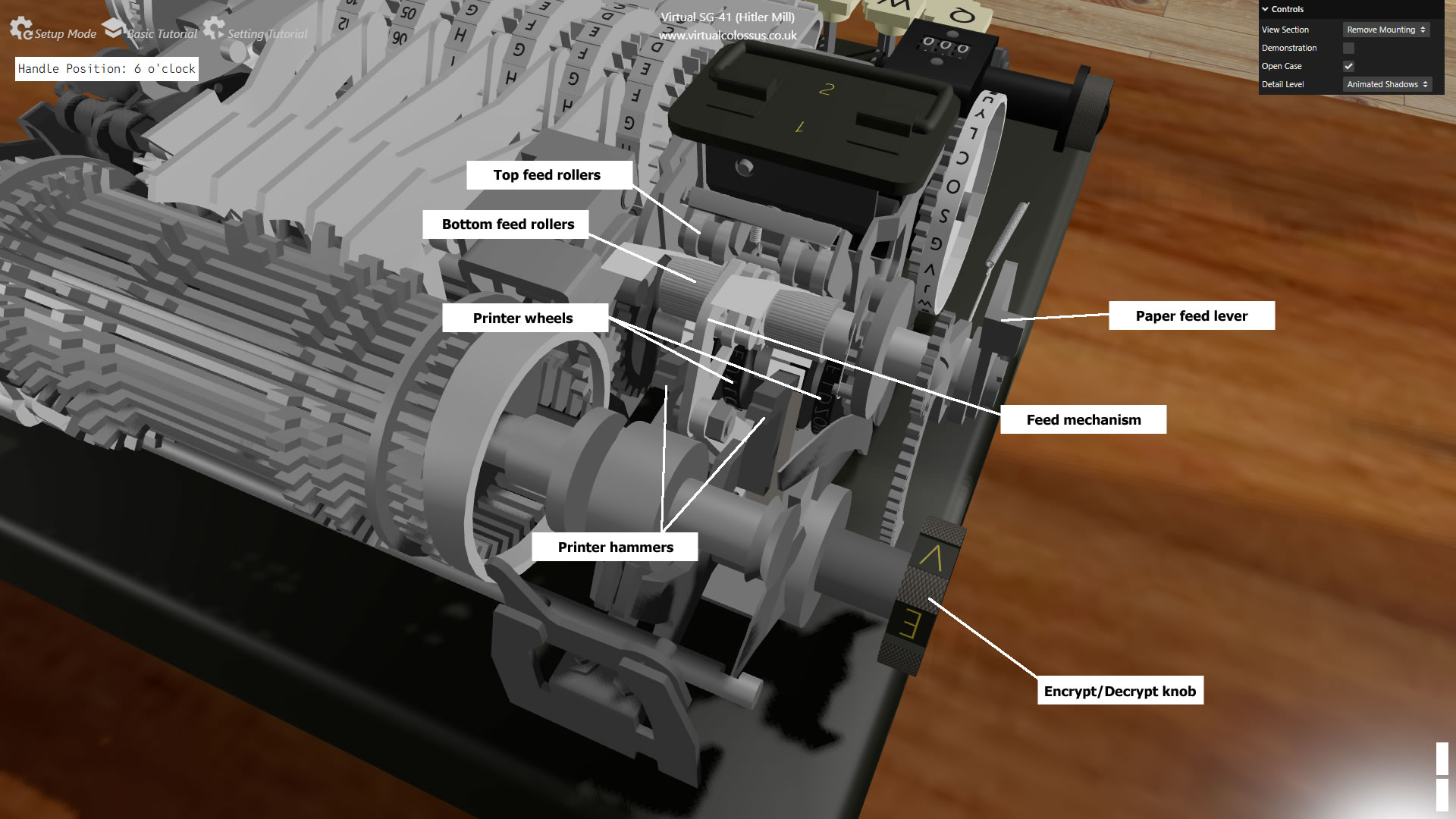
Internally, the SG 41 is densely packed with mechanical assemblies: a keyboard and linkage system, a complex gearing train, six pin wheels with movable pins, sensing arms that read those pins, a drum/cage that coordinates motion, and a dual printer with paper feed and ink system. The chassis is built like a typewriter frame, with covers that can be removed for maintenance and key setup. Most of the cryptologic logic is embodied in the relative stepping of the pin wheels and the way their patterns are sensed and translated into character shifts.
The keyboard mechanism
Each key on the SG 41 keyboard is mechanically linked to a set of levers that selects the plaintext character and unlocks the crank handle. The key press does not directly choose the cipher letter, but raises the lever with a catch on the end to underneath the print head driving cylinder.
When the crank is turned, the mechanism engages a system of gears that coordinates the print head driving cylinder to turn a full 360 degrees. This cylinder has 26 lugs around it's circumferance which are set to catch on any of the raised levers, a slip gear then means that the cylinder is held in that position until the full rotation is completed.
The positioning of the lugs on the print cylinder seem randomly placed, but actually, each lug corresponds in position to the matching letter on the plain text print wheel for that key, meaning that the plain text print wheel is turned and held to the same letter as the key.
A spring-loaded bar at the rear of the levers catches and holds the pressed key in its down position and a system of ball bearings at the front mean that only one key can be depressed at a time. The only way to release a key once pressed therefore is to turn the handle a full rotation so that the key block is released.
The obvious question that always gets asked is "Why is the J key red?". Notice that the keyboard only has 26 letter keys, there is no spacebar! The J key was used in place of a space character (eg SECRETJMESSAGE). Historically, in many hand ciphers, the I and J letters have been used as single character I thereby giving enciphering grids a nice even 25 letters of the alphabet to use in a 5x5 format. In German, the J is rarely used in text (0.24%-0.27%) and if replaced with the letter I, is generally still understandable in context, eg "Es ist das Iahr 2026" instead of "Es ist das Jahr 2026" (It is the year 2026).
Handle and gearing
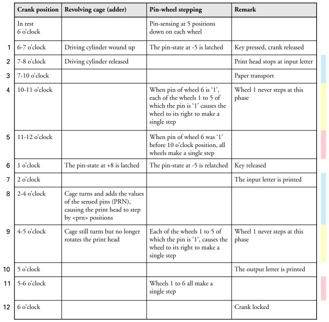
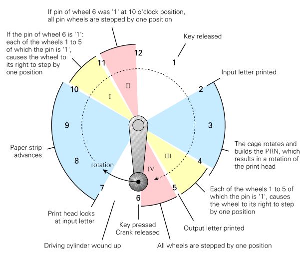
The large crank handle on the right side gives the SG‑41 its “Hitlermühle” (Hitler mill) nickname. Turning the crank drives a gear train that synchronizes all moving parts: pin‑wheel stepping, sensing, drum rotation, printer actuation, and paper feed. The gearing ensures that one full crank cycle corresponds to one complete encryption/decryption step.
The handle is locked and cannot be turned until a key is pressed first at which point it is released for a single 360 degree turn at which point the key will be released and the lock re-engaged.
The handle is normally stowed away and can be unfolded into the active position. It can then be folded away to reduce the size of the complete machine ready for fitting back into it's carry box.
From cryptomuseum.com, Klaus Kopacz & Paul Reuvers, Schlüsselgerät 41. https://www.cryptomuseum.com/pub/files/CM_SG41.pdf
From cryptomuseum.com, Klaus Kopacz & Paul Reuvers, Schlüsselgerät 41. https://www.cryptomuseum.com/pub/files/CM_SG41.pdf
Rotors and pins
Instead of wired electrical rotors like Enigma, the SG 41 uses pin wheels—discs with a series of positions around their circumference, each position holding a movable pin that can be set to active or inactive. There are six such wheels, each with a different number of positions, creating a very long combined period when all wheels are considered together. The pattern of active pins across all wheels forms the core of the key: by changing which pins are set, the operator defines a new pseudo random sequence of shifts. The wheels step in a non trivial pattern, further increasing complexity.
| 1 | 2 | 3 | 4 | 5 | 6 | |
|---|---|---|---|---|---|---|
| 25 | Z | Z | ||||
| 24 | Y | Y | 24 | 57 | ||
| 23 | X | X | X | X | 23 | 55 |
| 22 | W | W | W | W | 22 | 52 |
| 21 | V | V | V | V | 21 | 50 |
| 20 | U | U | U | U | 20 | 47 |
| 19 | T | T | T | T | 19 | 45 |
| 18 | S | S | S | S | 18 | 42 |
| 17 | R | R | R | R | 17 | 40 |
| 16 | Q | Q | Q | Q | 16 | 37 |
| 15 | P | P | P | P | 15 | 35 |
| 14 | O | O | O | O | 14 | 32 |
| 13 | N | N | N | N | 13 | 30 |
| 12 | M | M | M | M | 12 | 27 |
| 11 | L | L | L | L | 11 | 25 |
| 10 | K | K | K | K | 10 | 22 |
| 9 | I | I | I | I | 09 | 20 |
| 8 | H | H | H | H | 08 | 17 |
| 7 | G | G | G | G | 07 | 15 |
| 6 | F | F | F | F | 06 | 12 |
| 5 | E | E | E | E | 05 | 10 |
| 4 | D | D | D | D | 04 | 07 |
| 3 | C | C | C | C | 03 | 05 |
| 2 | B | B | B | B | 02 | 02 |
| 1 | A | A | A | A | 01 | 00 |
The table above shows the letters around the edge of each of the six pin-wheels and also the number of pins on each. The first two have 25 pins, the middle two have 23 and the right-hand two have 24 pins. The first four have letters at each setting (note that the letter J has been dropped for the same reason as shown in the keyboard description above) while the last two have numeric values. The 5th pin-wheel has incrementing numbers from 01-24 while the 6th has numeric values from 00-55 with intermittant steps between them.
Sensing levers
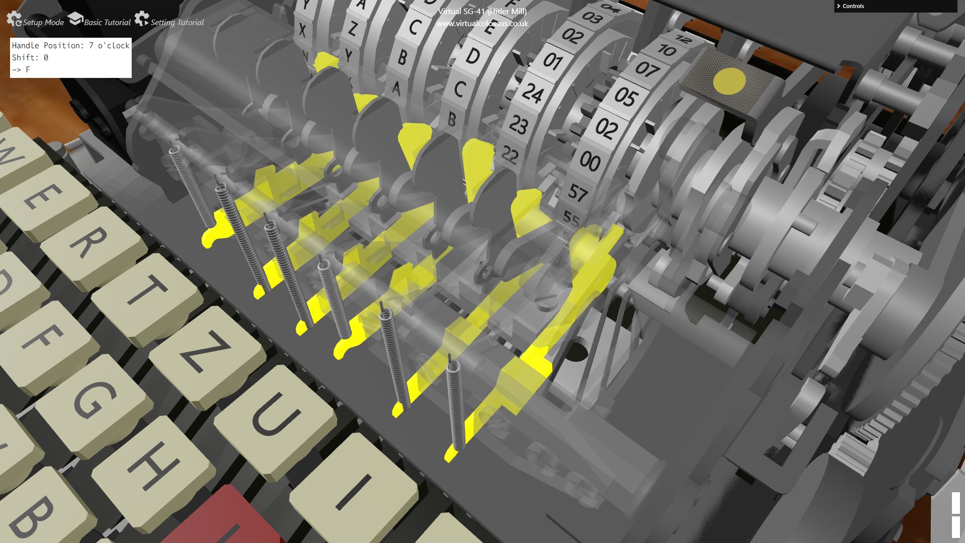
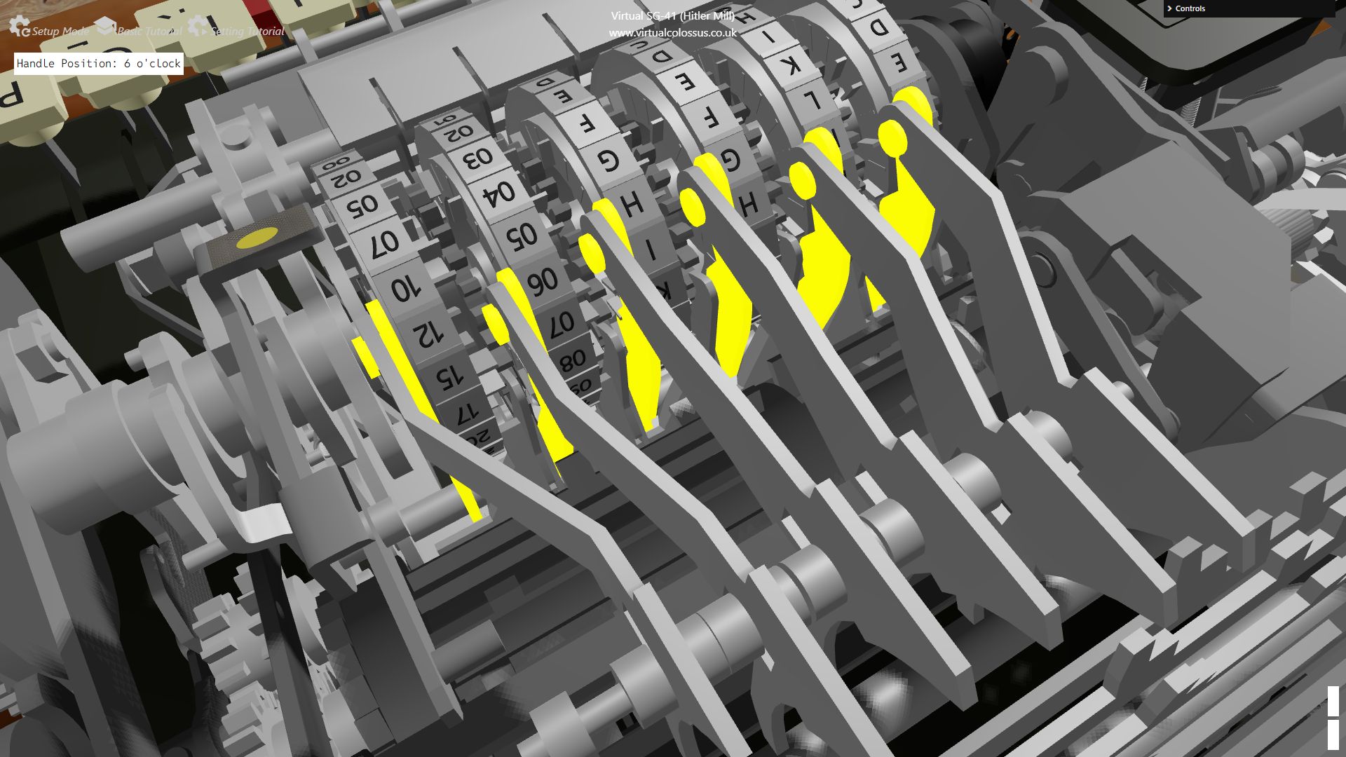
There are two positions that are checked on the pin-wheels with sensing levers, each with a different function. The first is 5 positions forward from where the letter is visible in the front window of the machine which controls the wheel stepping (eg if the window is showing A, the sensing position is from letter W). The second sensing position is 8 positions back from the window, and these are used to generate the PRNG value from the cage, stepping the print head forward to the cipher letter (eg for letter A in the window, the sensing position is letter H).
Behind the pin wheels is a bank of sensing arms or feelers that ride over the pin surfaces as the wheels rotate. When a sensing arm encounters an active pin, it is displaced, which is then translated into a mechanical signal via a set of sickle-shaped levers to the drum/cage at the rear, contributing to the total shift value for that step. Multiple sensing arms read multiple wheels simultaneously, and their combined displacements are summed into a net offset applied to the character being processed. This mechanical sensing replaces electrical contacts and wiring, making the SG 41 robust and less sensitive to moisture or dirt.
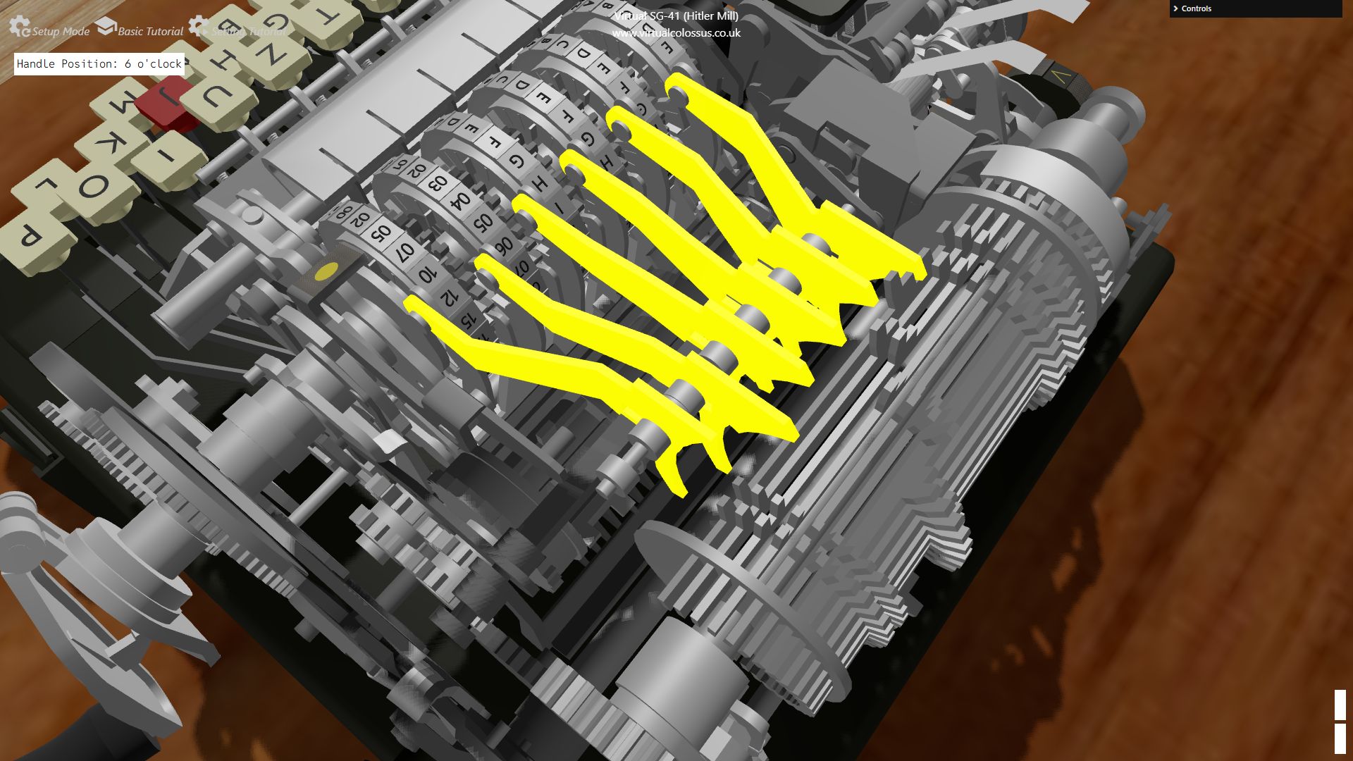
Unlike on the Hagelin M-209, this doesn't translate into a simple active/inactive state when reading the lugs on the drum though, the actual mechanism is actually much more complex as will be shown below.
Drum/Cage
The drum or cage is the main PRNG (Pseudo Random Number Generator) mechanic that actually enciphers our input letter, it has 25 spring-loaded bars with fixed position lugs mounted on them.
As the drum rotates a full 360 degrees, each of the lugs on the 25 bars comes into contact with the sickle-shaped levers fixing the bar into one of three positions. At the end of the bar is a lug which, when in the correct centre position, acts as a tooth to turn a gear which rotates the print wheel letter cylinder on one step.
The first bar on the drum has just one lug in line with the first wheel, the next two bars have a lug in line with the second wheel. Then, the next four bars have lugs for the third wheel with eight bars for the fourth wheel. For the final set of activating lugs for wheel five, the last ten bars have lugs, making a total of 25. As the drum rotates, the bars drop off a fixed, sloped edge at the left-hand side of the cage so that each bar then tries to move into it's spring-loaded left hand position, catching on the active/inactive sickle-shaped levers.
The first five levers (from left to right) all act the same while the sixth has a special inverting feature which greatly increases the complexity of the PRNG mechanism, making it much harder for a potential cryptographer to decrypt a captured message. The mechanism for the lever/bar/lug interaction is shown below.
Printers / Paper feed
The SG 41 includes a dual printing unit that outputs plaintext and ciphertext simultaneously on narrow paper tapes. Each character is printed by a mechanism including a pre-inked typewheel which is struck by a spring-loaded hammer through the tape. A dedicated paper feed mechanism advances the tapes one character position per cycle, driven by the same crank and gear train that powers the rest of the machine. This design eliminates the need for visual lamp reading and manual transcription, reducing operator errors and providing a durable record of both original and enciphered text.
Two sets of print wheels are available, one set for enciphering and one set for deciphering. A cam which rotates with the main drum/cage activates first the plain text spring-loaded hammer once the selected keyed letter is in place, then once the cage has rotated setting the enciphered letter, the second hammer fires. The plain text is always printed on the right-hand tape (looking from the front of the machine) while the enciphered/deciphered characters are on the left hand tape.
To feed the two paper tapes, the operator has two main functions: firstly, the paper advance lever and secondly, the paper release button.
The paper advance uses the pressure rollers to advance both paper tapes a set amount while the paper release removes the top rollers from the bottom ones allow the tape to simply be pulled out and torn off against the paper output glass
Stepping mechanism
The stepping mechanism controls how and when each pin wheel advances. Unlike simple odometer style stepping like in Enigma, the SG 41 uses a more complex scheme in which certain wheels step conditionally based on the state of others, producing an irregular, pseudo random progression. There are two places during a single letter encryption (the handle turns a full 360 degrees) where the rotors can step, one before the encryption and one afterwards. At each of the two stepping sections, the rotors can be stepped between 0 and 2 steps with there always being at least one single step overall.
Each of the rotors 2-6 have a follower on the rotor to their left, picking up the value of the active/inactive pin, which can block some of the movement with rotor 6 also having an overall blocking mechanism. The full astounting mechanism can be seen on the videos below. This very complex stepping mechanism significantly strengthens the cipher compared to regular rotor stepping.
How the rotor stepping works
Encryption / Decryption
The SG 41 implements a polyalphabetic substitution based on the combined output of the pin wheels. For each keypress, the machine does the following steps:
- Step 1: The pin wheels advance according to the initial stepping rules.
- Read pin pattern: Sensing arms detect which pins are active.
- Compute shift: A mechanical linkage and the drum/cage lugs sum these signals into a net shift value.
- Apply shift: The plaintext character (from the keyboard) is shifted within the machine’s alphabet to produce the ciphertext character.
- Print: Both plaintext and ciphertext are printed on their respective tapes.
- Step 2: The pin wheels advance according to the stepping rules.
While the system may, at first glance, look similar to that of the Hagelin M-209 (see Virtual Hagelin M-209), it greatly enhances that mechanism. Rather than a simple either on/off value to each lug on the bars of the cage, each lug for the first five rotors have two steps which catch both on the active and inactive levers linked to the rotor pins. The sixth rotor, if active, can also impart an inverse effect which greatly increases the complexity of the encryption.
The first rotor has a single lug, the second two, the third has four lugs, the fourth has eight and the fifth has ten lugs. Each of the lugs, if active, steps the print rotor on one step from the initial entered character meaning a total of 25 steps can be made.
The video below runs through the full encryption detail showing you how this was achieved on the SG-41
Ink Cartridge
The printing system uses an ink ribbon or ink roller (often described as an ink cartridge in modern terms) to transfer ink to the paper tapes. The cartridge is mounted near the type elements so that each hammer strike presses the paper against the inked surface. Over time, the ink medium must be replaced or re inked to maintain legible output. The design allows relatively quick replacement in the field, similar to typewriter maintenance, without disturbing the cryptologic components.
Paper Drawer
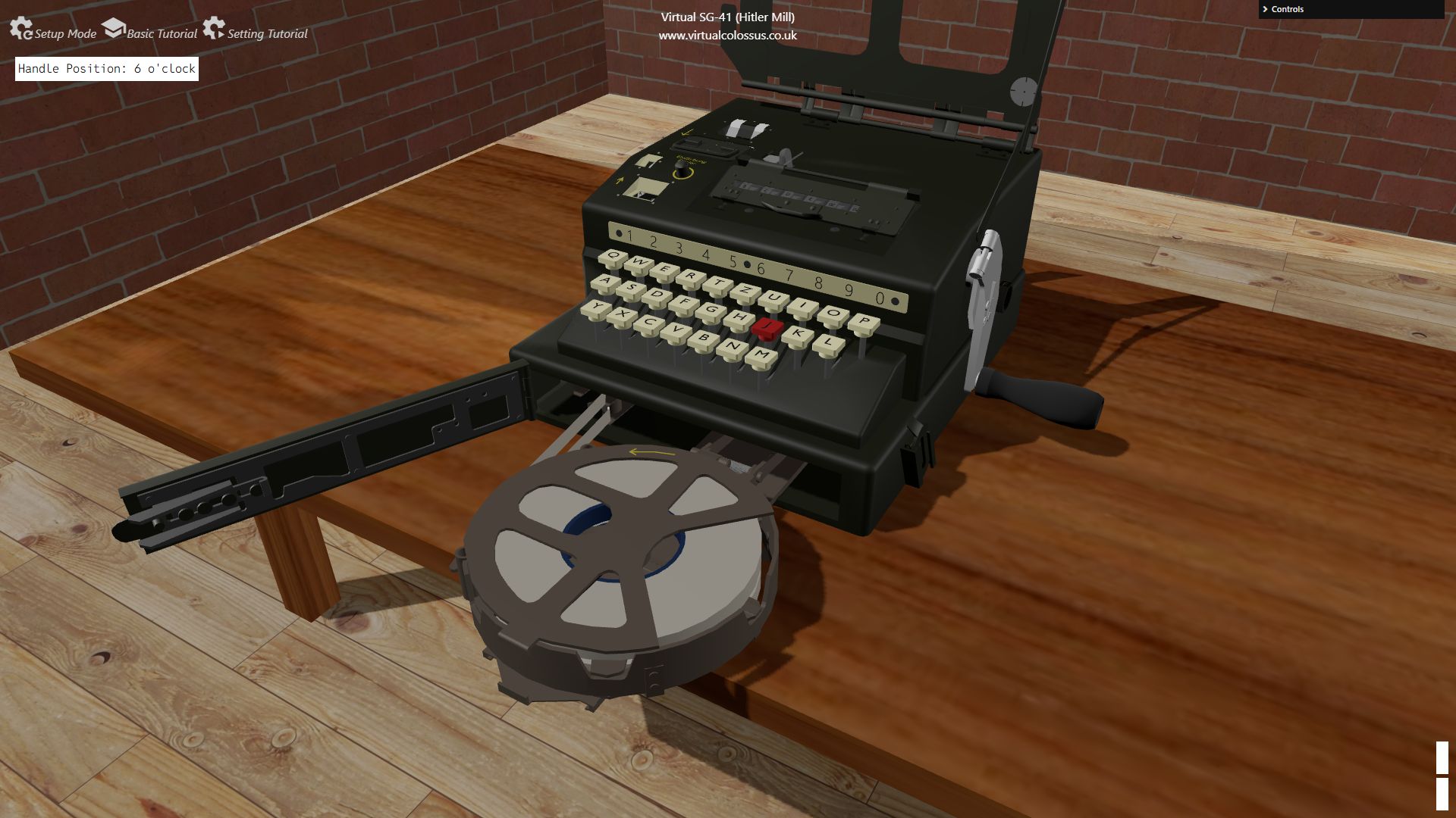
The SG 41 can hold two paper tape reels in a small compartment or “drawer” area where the tapes are stored and guided into the feed path. The operator loads fresh rolls of narrow paper tape, one on top of the other, then threads them through the guide rollers and between the printer hammers and print wheels. The drawer like compartment keeps the paper protected and organized, while still allowing easy access for loading.
Counter
A mechanical counter is integrated into the machine to track the number of characters processed or crank cycles completed. This helps operators monitor message length, detect anomalies in operation, and sometimes verify that a given key setting has not been overused. The counter is driven by the same motion that advances the stepping mechanism, ensuring that each encryption/decryption step increments the count reliably.
A counter reset dial allows the number to be reset back to 000 before starting a new message
Reset Mechanism
The SG-41 also has a mechanism which resets all the pins to inactive. This could have been either just for resetting the pins ready for setting up the next internal key, or for security, allowing the machine to be reset should the be the possiblity of capture.
First you sets the F/L knob on the right-hand side of the machine to L (Löschen or Delete) from the normal operate mode F (Funktion), then hold the lever on top of the SG-41 across to the left. This pushes a set of levers across onto the side of the rotors which pushes the pins to the left. The F/L knob releases the keyboard lock so the handle can be rotated without having to press a key each time. The handle would then be turned 25 full revolutions so all of the pins are reset. Lastly, the F/L knob and Löschen lever are set back and the counter reset.
How was this simulation created?
Over the past year I’ve been rebuilding the SG‑41 (“Hitlermühle”) as a fully interactive 3D simulation. It’s a machine that doesn’t get much attention compared to Enigma, partly because so few survived and partly because its internal mechanics are complicated.
I wanted to create something that wasn’t just a visual model but a functional reconstruction:
- every wheel, lever, and pawl is animated based on the real mechanism
- the stepping logic is implemented from historical documentation
- you can type plaintext and watch the machine encrypt in real time
- the whole thing runs in the browser with no plugins
This project started as a way to understand how the SG‑41 actually worked, and it turned into a deep dive into mechanical cryptography, wartime engineering constraints, and some surprisingly elegant design choices.
Creating the 3D models
The information about the SG-41 first came from one of my favourite sites on the internet, https://www.cryptomuseum.com. This gives a historic overview of the machine along with some photos and details of the mechanism. https://www.cryptomuseum.com/crypto/sg41/
One very important article on that site to this simulation is an article written by Klaus Kopacz & Paul Reuvers, Schlüsselgerät 41 dated Crypto Museum, 6 February 2021. This article is an in-depth full technical description of a real SG-41 machine that they managed to view and document. This gave a great detailed overview of how the mechanism works and this simulation would not have been possible without this initial information. Klaus Kopacz & Paul Reuvers, Schlüsselgerät 41
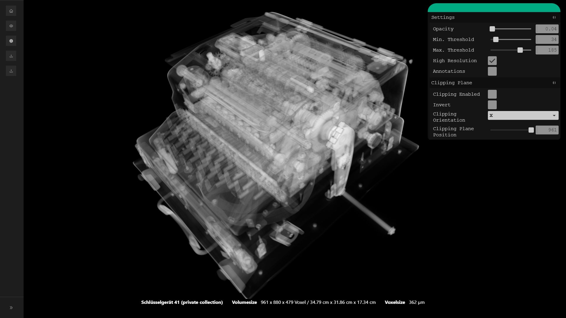
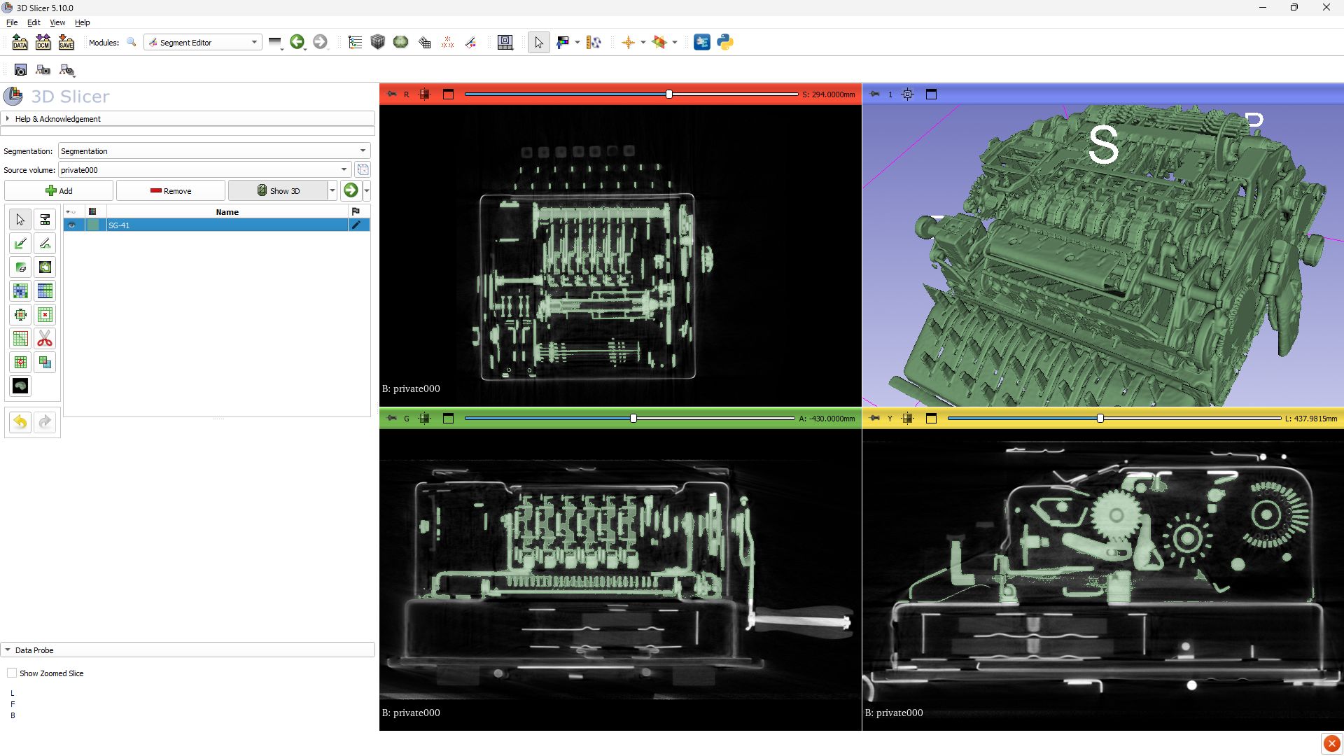
I first saw an initial view of the interior of the SG-41 when I found that the Deutches Museum had, between 2020-2023, completed a full computed tomography of many of their cipher machines. Since computed tomography (CT) is based on X-ray technology, objects can be scanned three-dimensionally to show interior detail not normally visible. There are two SG-41 machines and an SG-41Z numeric only machine which you can view in full 3D and slice through to see the interiors in detail. https://digital.deutsches-museum.de/en/projects/3d-cipher/
The Deutches Museum have also given the CT data available for download which is like a pile of images all sliced through from top to bottom of the machine. After several attempts and a bit of resizing, I managed to load them into a free software called 3D Slicer https://www.slicer.org/. This application is primarily for viewing and extracting models from biological samples, but it also works well for hardware apparently!
I started to believe that it might be possible to maybe rebuild this machine into a working simulation, although initially, the amount of work required to understand, model and animate the entire machine seemed a huge hill to climb! I didn't at this point understand every part of the mechanism by any stretch of the imagination, but I felt that I had enough of an idea to begin and work out the rest as I worked.
3D Slicer allowed me to not only view the interiors as models, but to cut out sections allowing each component or group of components to be exported as a 3D mesh model. The full machine is very complex and mechanically packed in very closely, so the ability to chop out the case or sections to extract and view the mechanism I was interested in was perfect!
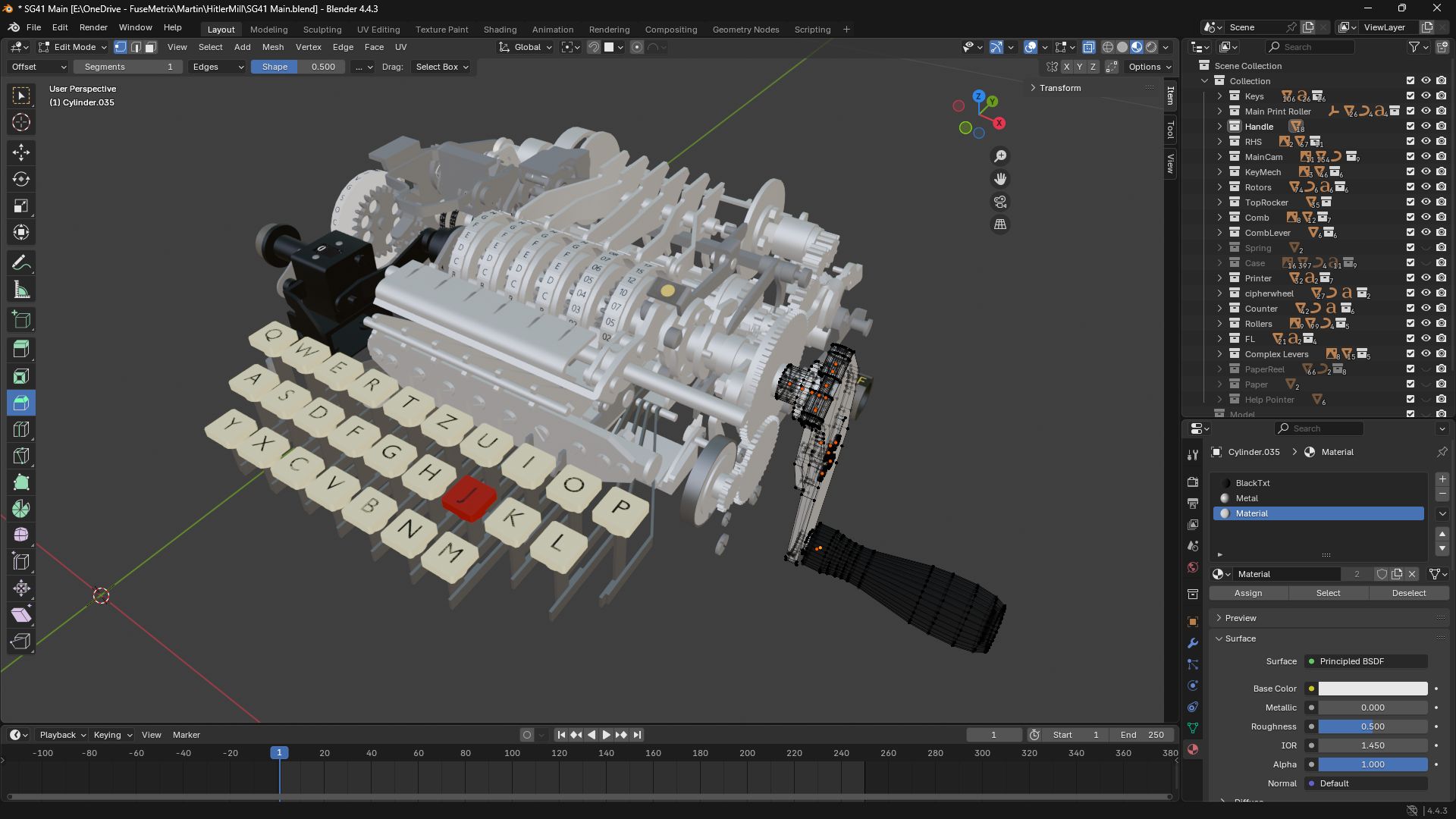
Once I had a selection of useable 3D models, I was able to import a few of these into Blender. Blender software is another amazing free appliation which I used to model each component by hand creating GLB model files ready for loading into the simulation.https://www.blender.org/
Each gear, cam, lever and spring was brought into Blender one at a time as a mesh object, resized and positioned to fit the full machine's layout. Once each block component was in place, I could then use Blender's object creation tools to create an accurate component as a 3D model which I could save as a GLTF file (Graphics Library Transmission Format) which is kind of like the JPG of 3D image files.
The final part of the process is to import these GLTF files into my HTML / JavaScript pages so they can be displayed within an internet browser. The rendering and animation is done by a JavaScript library called three.js https://threejs.org/. This library is also an amazing piece of free work that allows 3D objects to be rendered and animated with great speed, even on lower end machines. This part is important and I always wanted to give as many people the chance to try these machines out and learn about them, so being able to run them just in a browser without having to download a specific version for a type of machine is always high on my priority list.
One big help along the way was an invite by GCHQ to see their SG-41 machine which is in great condition. It allowed me to view and record the mechanism working fully, finding out about some questions that had been raised which are not always possible to answer fully just by looking at a static image. Many thanks to GCHQ for that opportunity.
A YouTube playlist of videos created during the building of this simulation which explain much of the functionality of the SG-41 as I discovered it : The Virtual SG-41 YouTube playlist